DC Tubular Motors: Multi-Channel Radio Control Motor Programming
Applies to these motors: TMDC-12-25-15-28-R, TMDC-12-25-07-34-R
Applies to these remotes: DCC-5A-RF, DCC-8A-RF, DCC-14A-RF
1. Preparing the RollerTrol™ motor:
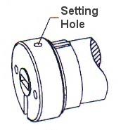
Figure 1: Set Program
Each RollerTrol™ motor has a a small hole on the outside edge of the cap at the wired end of the tubular motor. At the bottom of the hole is a small switch for activating the 'programming' mode of the motor.
You can feel a pronounced click when this switch is activated, when inserting a small screwdriver or similar item into the hole. You do not need to apply much pressure for this to be activated.
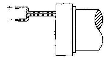
Figure 2: Wiring
Connect the motor to your power supply, then follow the instructions below to complete the programming.
A DC motor of this type normally reverses direction when the polarity is reversed, but please note that you can control the direction of the motor by programming (see step 5 below), so you do not have to pay too much attention to the polarity of the motor connection.
It is good practice, though, to connect them all the same way; the wires have a color coded pattern on them.
2. Preparing the Multi-Channel Radio Remote Control:
Slide the cover off the bottom of the remote control. A slight downward pressure with your thumb while you slide it off the bottom of the remote is all that is required.
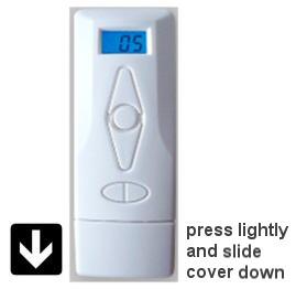
After removing this cover, you will see the battery compartment in the center of the exposed section. If the button battery is not installed, insert it now. Please pay attention to the battery polarity. The battery has a large plus + sign on one side (see diagram below) - this should be facing up, towards you.

There are 2 switches on either side of the battery holder. The left one is labeled 'confirm' and the right one is labeled 'limit'. Please familiarize yourself with the location of these switches.
3. Clear the motor memory:
- Insert screwdriver into hole and hold the switch down. After 3 seconds, you will hear a beeping sound.
- This will be the 'long beep' sound referred to in further instructions (beep ... beep ... beep).
- Continue to hold the switch down for a few more seconds, until you hear a series of short beeps.
- This will be the 'short beep' sound referred to in further instructions (beep.beep.beep).
- After you hear the short beeps, release the switch
The operation is done at this point - the memory has been cleared. You can reset the memory as many times as you like.
3. Assigning The Individual Channels:
- Press the channel button until you see channel 01 displayed on the remote.
- Insert the screwdriver into the motor 'programming' hole and hold the switch down for about 3 seconds. When you hear the long beeps (beep ... beep ... beep), release the screwdriver. The motor is now in programming mode and is waiting for its channel assignment.
- To complete the channel assignment, press the 'confirm' button inside the remote (left side). You will hear a series of short beeps almost immediately; release the button when you do.
At this point, the operation is complete - the motor is assigned to channel 1. You should be able to activate the motor normally when channel 1 is selected on the remote control.
4. Testing the Motor Direction:
You should be able to run the motor at this point - try the up/down/stop buttons. If the motor runs in the opposite direction to the one desired, you can reverse the motor direction:
- hold down the 'limit' switch, then hold down the stop button also.
- after a few seconds, you will hear the short beeps (beep.beep.beep)
- release both keys and test the motor again (it should run in the opposite direction).
4. Assigning Motor to 'ALL' Group:
Each motor can be assigned to the group control system, so that it will be selected when the remote is set to operate in 'Group Mode'. While in 'Group Mode', pressing the UP/DOWN/STOP buttons will control all motors in the group simultaneously.
This is done by pressing the 'Group' button so that 'AL' appears in the LCD display. The Group mode will also appear as you cycle through all the channels. Note that motors can be excluded from Group Mode by skipping this step.
If you later wish to exclude a motor that was previously assigned to the group mode, apply the 'clear memory' function to the motor described in step 1. You will have to re-apply channel assignment and travel limits if you do this.
4. Setting the Upper and Lower Travel Limits:
The travel limits of a RollerTrol™ motor can be set and changed at any time with the remote control; you do not have to touch the motor at all. The sequence is as follows:
Setting the Upper Limit:
- Press and hold down the 'Limit' button (figure 4) for 3 seconds, until you hear the 3 'long beeps'. This action places the motor into its limit programming mode.
- Press the UP button on the remote; the motor will move in the up direction at normal speed.
- When it gets close to the upper limit, press the STOP button. The motor now enters the 'Jog' mode.
- Press the UP or DOWN buttons to move the motor slightly in one direction or the other. You'll see the motor move in very short steps that are a small fraction of a full rotation. Use this mode to position your motor at the exact upper limit you desire.
- Press the 'Confirm' button. After you hear the 3 'short beeps', the upper limit has been set. The motor is still in 'programming mode' so that you can set the lower limit.
Setting the Lower Limit:
- Press the DOWN button on the remote; the motor will move in the down direction at normal speed.
- When it gets close to the lower limit, press the STOP button. The motor now enters the 'Jog' mode.
- Press the UP or DOWN buttons to move the motor slightly in one direction or the other. You'll see the motor move in very short steps that are a small fraction of a full rotation. Use this mode to position your motor at the exact lower limit you desire.
- Press the 'Confirm' button. After you hear the 3 'short beeps', the upper limit has been set. The motor is now back in normal running mode and you should be able to test the full excursion.
5. Repeat the above steps for each motor:
The process is the same for all motors in the group, but each one will normally be assigned to a different channel (although you CAN assign multiple motors to the same channel). Once the travel limits have been set, they will be observed for each individual motor, even when activated simultaneously in Group Mode with the ALL button.
We sincerely hope you enjoy using these advanced motors; if you have any questions, please feel free to contact us at any time!